9

This concerns the very nice answer of Altermundus in this question. I asked here on meta how to post this, and we agreed upon posting it as CW on meta.

First of all, very nice answer, especially that you try an automated version. I especially like the sphere. But there are some issues:

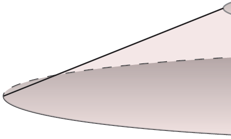
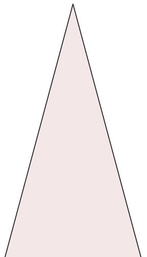
  • You connect the upper and lower face of the truncated cone by a line connecting both at their 0° and 180° position (as did I in my answer, ahem, ahem). This is okay for cylinders and speep truncated cones, but not for flat ones: \tikz \tkzTruncatedCone{5}{0}{1}; will look like this:

enter image description here

I'll try to math out an automated way (probably Andrew Stacey can help :D, I remember a great cylinder answer)

  • also, the lines are inconsistent: the upper circle is gray, the sides black, and the lower circle is half/half. This can be solved by first doing all the shadings and fillings, then the drawings.

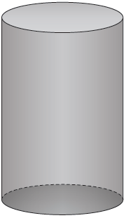
  • While the lower shading looks good, the upper one looks bad, it makes me think of an open tin can, not really a cylinder. I'll head for the kitchen and look for a can of beans or something to come up with a suggestion. Giving the top a lighter shading does the trick, something like this:
enter image description here

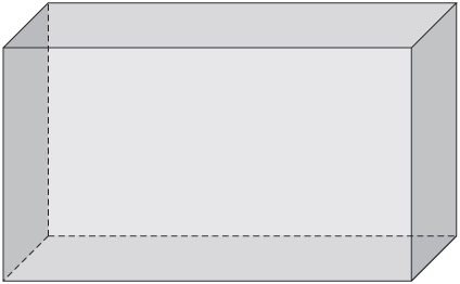
  • I both like and dislike your cuboid approach: While its a nice idea to make certain sets of sides lighter, I dont like it to be left/right. Do you plan to make this customizable, so that I can choose the colors (or opacities) for all three sets independantly? I did it, looks like this:

enter image description here

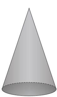
  • The upper part of the cone doesn't teally work: It can be improved by a left-to-right shading:
enter image description here enter image description here

I think it could use some shading of sorts, but I don't know yet how.

I hope this helps, I'll let you know if I come up with something for the truncated cone edge problem. The code for my improvement suggesions in in my answer to the question linked.

3
  • Am I blind, or isn't there any check box for "community wiki" on Meta? Commented Jul 6, 2012 at 21:08
  • Only mods can make questions CW: I've done that.
    – Joseph Wright Mod
    Commented Jul 6, 2012 at 21:11
  • @JosephWright: Ah, good to know, thanks. Commented Jul 6, 2012 at 21:31

1 Answer 1

3

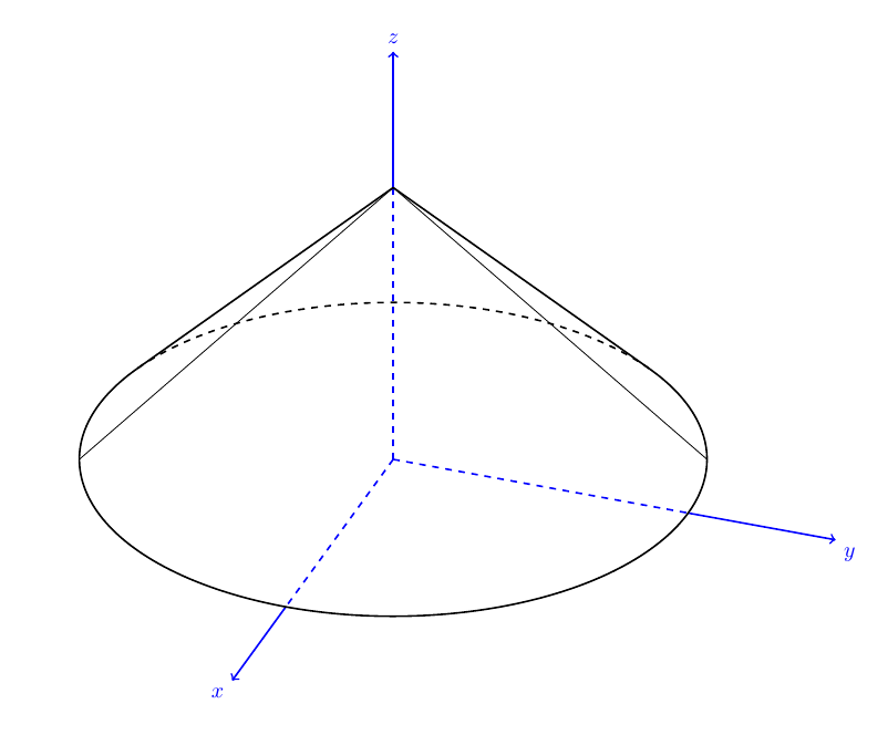
A little late after the question, still, may be it will help someone -- there is my solution for the bad edge cone problem:

\documentclass[]{article}
\pagestyle{empty}

\usepackage{calc}
\usepackage{tikz,tikz-3dplot}
\usepackage{geometry}

\begin{document}

%polar coordinates of visibility
\pgfmathsetmacro\th{60}
\pgfmathsetmacro\az{110}

\tdplotsetmaincoords{\th}{\az}

%parameters of the cone
\pgfmathsetmacro\R{1}
\pgfmathsetmacro\v{1}


\begin{tikzpicture} [scale=5, tdplot_main_coords, axis/.style={blue,thick}]

\coordinate (O) at (0,0,0);

%draw axes
    \draw[axis,dashed] (0,0,0) -- (\R,0,0);
    \draw[axis,->] (\R,0,0) --(1.5*\R,0,0) node[anchor=north east]{$x$};
    \draw[axis,dashed] (0,0,0) -- (0,\R,0);
    \draw[axis,->] (0,\R,0) --(0,1.5*\R,0) node[anchor=north west]{$y$};
    \draw[axis,dashed] (0,0,0) -- (0,0,\v);
    \draw[axis,->] (0,0,\v) --(0,0,1.5*\v) node[anchor=south]{$z$};

% % computation of tangential points
\pgfmathsetmacro\cott{{cot(\th)}}
\pgfmathsetmacro\fraction{\R*\cott/\v}
\pgfmathsetmacro\angle{{acos(\fraction)}}

% % angles for transformed lines
\pgfmathsetmacro\PhiOne{180+(\az-90)+\angle}
\pgfmathsetmacro\PhiTwo{180+(\az-90)-\angle}

% % coordinates for transformed surface lines
\pgfmathsetmacro\sinPhiOne{{sin(\PhiOne)}}
\pgfmathsetmacro\cosPhiOne{{cos(\PhiOne)}}
\pgfmathsetmacro\sinPhiTwo{{sin(\PhiTwo)}}
\pgfmathsetmacro\cosPhiTwo{{cos(\PhiTwo)}}

% % angles for original surface lines
\pgfmathsetmacro\sinazp{{sin(\az-90)}}
\pgfmathsetmacro\cosazp{{cos(\az-90)}}
\pgfmathsetmacro\sinazm{{sin(90-\az)}}
\pgfmathsetmacro\cosazm{{cos(90-\az)}}

% % draw basis circle
\tdplotdrawarc[tdplot_main_coords,thick]{(O)}{\R}{\PhiOne}{360+\PhiTwo}{anchor=north}{}
\tdplotdrawarc[tdplot_main_coords,dashed,thick]{(O)}{\R}{\PhiTwo}{\PhiOne}{anchor=north}{}

% % displaying tranformed surface of the cone (rotated)
\draw[thick] (0,0,\v) -- (\R*\cosPhiOne,\R*\sinPhiOne,0);
\draw[thick] (0,0,\v) -- (\R*\cosPhiTwo,\R*\sinPhiTwo,0);

% % displaying original surface of the cone (rotated)
\draw[thin] (0,0,\v) -- (-\R*\sinazm,-\R*\cosazm,0);
\draw[thin] (0,0,\v) -- (-\R*\sinazp,+\R*\cosazp,0);

\end{tikzpicture}

\end{document}

enter image description here

2
  • How can I add label at the point (0,0,\v), (0,\R,0), (\R,0,0),...? Commented Oct 6, 2017 at 12:53
  • @toandhsp just add a line like \node at (\R,0,0) {test};
    – fales
    Commented Oct 9, 2017 at 17:04

You must log in to answer this question.

Not the answer you're looking for? Browse other questions tagged .